
TECHNOLOGY BOOK
An introduction to AIRSPEED's acoustic C-UAS sensing technology for Defence and Security professionals
A New Air Defence Challenge
Drones pose a significant threat on the battlefield due to their ability to conduct surveillance, gather intelligence, and carry out precision strikes with minimal risk to the operator. Their small size, agility, and low radar signature make them difficult to detect and counter using traditional air defence systems. Adversaries can use drones for reconnaissance, targeting enemy positions, or even deploying explosives in kamikaze-style attacks. Additionally, autonomous and radio-silent drones can bypass electronic warfare measures, further complicating defence efforts. Their affordability and accessibility make them a powerful tool for asymmetric warfare, allowing even non-state actors to challenge conventional military forces.
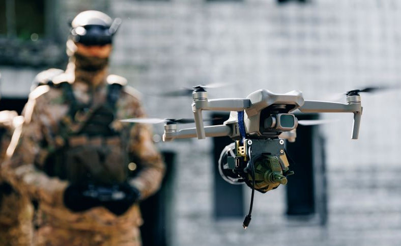
Military UAV operator launches drone with grenade to drop into enemy fortifications and trenches. (SHUTTERSTOCK IMAGES)
In civilian settings, drones present security risks to airports, critical infrastructure, and public events. Unauthorised drones can interfere with air traffic, potentially causing catastrophic accidents. They can also be weaponized for terrorist attacks or used for smuggling contraband across borders and into prisons. Privacy concerns are another issue, as drones equipped with high-resolution cameras and other sensors can be exploited for espionage, corporate surveillance, or stalking. The affordability and accessibility of drones make them an asymmetric threat, allowing even small groups or individuals to disrupt operations and challenge law enforcement and military defences. As drone technology advances, the need for effective countermeasures becomes increasingly urgent.
The Technology Landscape
Many traditional air defence systems are not optimised to detect and track small UAVs. In response to the growing drone threat, a range of new technologies has emerged. Today, most Counter-UAS (C-UAS) sensing relies on RF monitoring, detecting radio signals transmitted by either the drone or its operator. However, determined adversaries increasingly bypass these systems using autonomous drones or alternative command-and-control (C2) links, such as fibre optics, creating radio-silent “dark drones.”
Cameras remain valuable tracking tools, but their narrow field of view means they must be integrated with other sensors to reliably locate and follow targets. Dedicated counter-drone radar systems can provide long-range detection, but they are often costly, susceptible to jamming, and, as active sensors, can reveal the operator’s location, an important consideration in tactical environments.
Passive acoustic sensing mitigates some of these vulnerabilities, particularly in low-visibility or contested RF environments. Machine listening systems provide a complementary layer of capability, enhancing a broader, multi-sensor approach to airspace surveillance.
Many C-UAS solutions integrate technologies from multiple suppliers. Airspeed contributes as part of industrial consortia, helping to develop layered counter-drone systems tailored to complex operational requirements.

A counter-drone solution requires sensors, effectors and a command and control system.
The drone and counter-drone landscape is evolving rapidly. Over the next five years, the technology environment is likely to change significantly. For the past decade, passive RF surveillance has dominated the C-UAS sensing market. We anticipate a shift towards other passive modalities, particularly electro-optic and acoustic sensing, while millimetric radar will continue to maintain a strong role.
This trend reflects a broader move by adversaries toward radio-silent drones. Fibre-optic guided drones are already in widespread use to evade RF detection, and autonomous systems capable of completing missions without any RF signature are expected to become more prevalent within the next five years. Future conflict zones will see greater reliance on these autonomous, radio-silent systems, while the RF spectrum will be increasingly contested through jamming and other electronic warfare techniques.
The figure below highlights past and current trends in C-UAS sensing and provides insight into how these are likely to evolve in the near-term future.
CUAS Future Trends

Passive Distributed Acoustic Sensing

A network of AIRSPEED's TS-16 acoustic remote sensors at the British Army's AWE-24 excercise, Salisbury plain, UK.
Our solution deploys networks of passive acoustic sensors for wide-area coverage. Each sensor is equipped with an integrated mesh radio transceiver and GPS receiver, allowing it to quickly determine its position and seamlessly connect with other sensors.
Each unit provides a hemispherical sensing region, typically detecting and tracking small quadrotors within a 200–300 m range in rural environments—equating to a 30–70 acre coverage area per sensor. The detection footprint expands with additional sensors, creating a scalable network.
Our sensors function as both endpoints and repeaters within the mesh radio network, ensuring robust connectivity and eliminating concerns about range limitations. With a typical cost of £6,500 to £12,000 per unit, they offer an effective, cost-conscious solution for wide-area drone detection.
Sensor Fusion
The acoustic sensors estimate the target’s bearing and elevation angles with degree-level precision. However, direct range estimation is impractical due to variations in acoustic signal strength. In a networked setup, multiple sensors can triangulate the target’s position and altitude within a few meters by combining data from at least two sensors.
Real-time sensor fusion of data transmitted from a network of distributed acoustic sensors at AWE-24, Salisbury, UK.
A single mesh radio gateway receives target track messages from all sensors and forwards the data to a central server. The server then fuses the data, which consists of angles to the target from each sensor, by triangulating the target's position. The intersection points of these target directions are fed into a tracking algorithm that maintains the target’s Cartesian coordinates using a Kalman filter. This track information can then be relayed to third-party systems through standard data interfaces, such as SAPIENT or TAK Cursor-on-Target messages. Additionally, the server performs network discovery by broadcasting interrogation messages to the sensor network via the mesh radio, ensuring seamless communication and connectivity across the system.
Drone Acoustic Signature
Multirotors emit various acoustic signals, but the two dominant sources of noise are aeroacoustic noise and blade pass tones. Aeroacoustic noise is broadband white noise caused by moving air, making it difficult to distinguish from natural sounds like wind. In contrast, blade pass tones are more useful for drone detection.
Blade pass tones arise from the interaction between spinning rotor blades and the aircraft's static structure. Their fundamental frequency is proportional to rotor speed, typically ranging from 100 to 200 Hz for two- or three-bladed rotors. Harmonics of this frequency create a chord-like effect with multiple discrete frequencies, giving drone noise its characteristic "rasping" quality, often perceived as irritating.
Human perception of drone noise differs significantly from machine-based detection. Unlike machines, human hearing is subject to psychoacoustic effects and is not uniformly sensitive across all frequencies. As a result, one drone may seem louder than another simply because it emits noise in a frequency range where human ears are more responsive. Machine listening systems, however, remain neutral to such variations.

Received Time-Frequency spectrogram of a DJI Phantom quadrotor at various ranges to target.
Beyond detection, a drone’s acoustic signature provides valuable information about its characteristics. It can reveal the number of rotors, pitch imbalances, and rapid pitch variations. These factors help infer drone subclasses, estimate payload mass (as added weight can affect rotor pitch), and determine whether the drone is manually piloted or autonomously controlled.
Microphone Arrays

AIRSPEED's BK-16 large aperture microphone array, Westcott, UK, 2024
The sensor units feature an array of microphones, enabling the use of advanced phased-array signal processing techniques that effectively separate target sounds from ambient background noise. Using these microphone arrays, various direction-finding methods can be applied to accurately determine the spatial location of the target.
At longer target distances, the sensor primarily receives low-frequency tones, as these signals tend to propagate more effectively over greater ranges. Generally, increasing the size of the microphone array enhances the detection range, creating a design trade-off between sensor size and detection capability. In our designs, we prioritise target detection performance over compactness, resulting in larger sensor configurations that maximise detection range.
Our microphone arrays are configured to provide a hemispherical field of view, covering 360° azimuth and 90° elevation. This ensures the sensor has no blind spots and maintains consistent performance regardless of its orientation.
Microphones
Electret condenser microphone capsules are chosen over MEMS microphones for their superior performance, despite a more complex analogue electrical interface. Though MEMS microphones are popular due to their low cost, small size and ease of integration, the performance characteristics of traditional electret condensers make them better suited for far-field target detection.

Exploded view of a phantom-powered condenser microphone assembly produced by AIRSPEED
Each microphone capsule includes a waterproof acoustic vent, which effectively prevents water and dust from entering the microphone, ensuring durability in various environments. Additionally, a reticulated foam wind shield reduces low-frequency interference caused by wind noise by creating a stable region of air around the microphone diaphragm.
Each microphone unit incorporates a discrete transistor preamplifier, powered by phantom power supplied by the sensor signal processing unit. This combination results in a highly robust audio capture unit characterized by ultra-low noise and low distortion. These attributes are essential for the long-range detection of drones, where signal clarity is critical.
Signal Processing Hardware
Each sensor features advanced electronic signal processing hardware that converts audio signals from a 16-channel microphone array into precise target tracking data. Equipped with NVIDIA GPUs capable of performing 70 trillion mathematical operations per second, the sensors operate in real-time at approximately 10 frames per second.
Signal processing hardware comprising an NVIDIA GPU and custom broadcast quality audio capture boards.
The audio signals are captured using broadcast-grade analogue-to-digital converters, offering a signal-to-noise ratio exceeding 120 dB. This high level of processing power and audio capture performance is crucial for detecting, identifying, and tracking drone targets, even when the received signals are exceptionally weak.
We are able to fabricate electronic hardware in small quantities, and work with trusted partners for larger manufacturing requirements.

A small batch of signal processing electronic assemblies produced in-house.
Signal Processing Algorithms
Engineering dashboard generated by a remote sensor whilst tracking a small drone.
Each sensor resolves azimuth and elevation angles within a hemispherical envelope at 1° resolution, using array signal processing to create an acoustic camera that updates at 10 frames per second. This is achieved through Time Difference of Arrival (TDOA), which measures coherence rather than steered response power, enhancing long-range performance.
For tracking, local peaks in the sound field image are assigned to tracks based on angular proximity. Confirmed tracks are classified via a Neural Network, using a rolling 3-second time-frequency spectrogram (1.8 kHz bandwidth, <2 Hz resolution). A beamformer follows the target’s position, feeding the spectrogram into a pre-trained CNN for classification. The system tracks multiple targets simultaneously.
Once detected, target track messages—including timestamp, track ID, azimuth, elevation, and classification probability—are transmitted via mesh radio at 10 FPS. Target class masks control which classifications are reported.
For precise triangulation, each sensor uses GPS for self-location, and manual magnetic north alignment ensures accurate orientation.
Microphone Array Performance Modelling
Selecting an optimal microphone array geometry for a specific application is often considered a complex and nuanced challenge. To address this, we have developed specialised software tools that evaluate the performance of a given microphone array configuration. The software works by calculating the 3D beampattern of the array across a range of frequencies, generating key performance metrics such as gain, beamwidth, and bandwidth.
Simulated beam pattern of a spherical microphone array at 1200 Hz.
To identify the best array geometry for a given operational requirement, we employ a Monte Carlo technique that systematically sweeps the geometric parameters of the microphone positions. This optimisation process is significantly accelerated by leveraging general-purpose GPU processing for the beampattern calculations, allowing the solution space to be explored comprehensively within a matter of hours.
A parametric sweep of array geometry parameters
Sensor Range Performance
The image below illustrates how variations in microphone array configuration affect directivity and range, while using broadly the same signal processing equipment. In all test cases, the target was a small DJI Phantom 3 quadrotor. For this class of target, detection ranges between 170 m and 340 m are achievable. It should be noted, however, that sensor range is highly variable and depends strongly on ambient acoustic noise levels, the loudness of the target, and prevailing atmospheric conditions. As an example, using the same equipment it is possible to maintain a track on a louder target such as a helicopter at ranges of several kilometres. It is also important to differentiate range performance for detection and tracking. Whilst a detection could be fleeting, maintaining a target track requires more persistent target observations. For this reason, very simple binary target detectors can sometimes outrange more complex direction finding sensors.

Trade-off between sensor Field of View and target detection range
Range performance should not be considered in isolation. Sensor footprint is equally important. Where area coverage is the primary objective, shorter range omnidirectional sensors can outperform longer range systems with a narrower field of view. In general, sensor field of view can be traded against range, and vice versa. A number of methods exist for increasing directivity, including the use of horns, reflectors, and phased arrays. These approaches, however, typically increase sensor size, complexity, and cost.
At its core, acoustic detection is a signal-to-noise ratio problem. And fundamentally, acoustic sensors will always offer shorter ranges than radar or EO sensors, simply due to the physics of how sound propagates through air, which is an inherently lossy medium for sound, when compared with light or radio waves. Signal attenuation over range is primarily caused by both geometric spreading and atmospheric absorption - the latter dominating at ranges over a few hundred meters to target. The target becomes undetectable when the received signal falls below the effective acoustic noise floor. Sensor detection range and footprint scale with target loudness as shown below:

Variations in detection range with target loudness.